Turbine flow meter use a free-spinning turbine wheel to measure fluid velocity, much like a miniature windmill installed in the flow stream.
Turbine Flow Meter Working Principle
Turbine Flow Meter is a volumetric measuring turbine type. The flowing fluid engages the rotor causing it to rotate at an angular velocity proportional to the fluid flow rate.
The angular velocity of the rotor results in the generation of an electrical signal (AC sine wave type) in the pickup. The summation of the pulsing electrical signal is related directly to total flow.
The frequency of the signal relates directly to flow rate. The vaned rotor is the only moving part of the flow meter.

The Turbine flow meter (axial turbine) was invented by Reinhard Woltman and is an accurate and reliable flow meter for liquids and gases.
It consists of a flow tube with end connections and a magnetic multi bladed free spinning rotor (impeller) mounted inside; in line with the flow.
The rotor is supported by a shaft that rests on internally mounted supports.
The Supports in Process Automatics Turbine Flow Meters are designed to also act as flow straighteners, stabilizing the flow and minimizing negative effects of turbulence.
The Supports also house the unique open bearings; allowing for the measured media to lubricate the bushes – prolonging the flow meters life span.
The Supports are fastened by locking rings (circlips) on each end.

The rotor sits on a shaft ,which in turn is suspended in the flow by the two supports. As the media flows, a force is applied on the rotor wings.
The angle and shape of the wings transform the horizontal force to a perpendicular force, creating rotation. Therefore, the rotation of the rotor is proportional to the applied force of the flow.
Because of this, the rotor will immediately rotate as soon as the media induces a forward force. As the rotor cannot turn thru the media on its own, it will stop as soon as the media stops.
This ensures an extremely fast response time, making the Turbine Flow Meter ideal for batching applications.

A pick-up sensor is mounted above the rotor. When the magnetic blades pass by the pickup sensor, a signal is generated for each passing blade.
This provides a pulsed signal proportional to the speed of the rotor and represents pulses per volumetric unit.; and as such the flow rate too.

The fundamental design goal of a turbine flow meter is to make the turbine element as free-spinning as possible, so no torque will be required to sustain the turbine’s rotation.
If this goal is achieved, the turbine blades will achieve a rotating (tip) velocity directly proportional to the linear velocity of the fluid, whether that fluid is a gas or a liquid:

Turbine Flow Meter Construction
A cut-away demonstration model of a turbine flow meter is shown in the following photograph. The blade sensor may be seen protruding from the top of the flow tube, just above the turbine wheel:

Note the sets of “flow conditioner” vanes immediately before and after the turbine wheel in the photograph. As one might expect, turbine flow meters are very sensitive to swirl in the process fluid flow stream.
In order to achieve high accuracy, the flow profile must not be swirling in the vicinity of the turbine, lest the turbine wheel spin faster or slower than it should to represent the velocity of a straight-flowing fluid.
A minimum straight-pipe length of 20 pipe diameters upstream and 5 pipe diameters downstream is typical for turbine flow meters in order to dissipate swirl from piping disturbances.
Mechanical gears and rotating cables have also been historically used to link a turbine flow meter’s turbine wheel to indicators.
These designs suffer from greater friction than electronic (“pickup coil”) designs, potentially resulting in more measurement error (less flow indicated than there actually is, because the turbine wheel is slowed by friction).
One advantage of mechanical turbine flow meters, though, is the ability to maintain a running total of gas usage by turning a simple odometer-style totalizer.
This design is often used when the purpose of the flow meter is to track total fuel gas consumption (e.g. natural gas used by a commercial or industrial facility) for billing.
The mathematical relationship between fluid velocity and turbine tip velocity – assuming frictionless conditions – is a ratio defined by the tangent of the turbine blade angle:

For a 45 deg blade angle, the relationship is 1:1, with tip velocity equaling fluid velocity. Smaller blade angles (each blade closer to parallel with the fluid velocity vector) result in the tip velocity being a fractional proportion of fluid velocity.
Turbine tip velocity is quite easy to sense using a magnetic sensor, generating a voltage pulse each time one of the ferromagnetic turbine blades passes by.
Traditionally, this sensor is nothing more than a coil of wire in proximity to a stationary magnet, called a pickup coil or pick-off coil because it “picks” (senses) the passing of the turbine blades.
Magnetic flux through the coil’s center increases and decreases as the passing of the steel turbine blades presents a varying reluctance (“resistance” to magnetic flux), causing voltage pulses equal in frequency to the number of blades passing by each second.
It is the frequency of this signal that represents fluid velocity, and therefore volumetric flow rate.
In an electronic turbine flow meter, volumetric flow is directly and linearly proportional to pickup coil output frequency. We may express this relationship in the form of an equation:
![]()
Where,
f = Frequency of output signal (Hz, equivalent to pulses per second)
Q = Volumetric flow rate (e.g. gallons per second)
k = “K” factor of the turbine element (e.g. pulses per gallon)
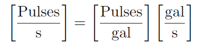
Dimensional analysis confirms the validity of this equation. Using units of GPS (gallons per second) and pulses per gallon, we see that the product of these two quantities is indeed pulses per second (equivalent to cycles per second, or Hz):
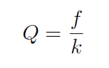
Using algebra to solve for flow (Q), we see that it is the quotient of frequency and k factor that yields a volumetric flow rate for a turbine flow meter:
The inherent linearity of a turbine flow meter is a tremendous advantage over nonlinear flow elements such as venturi tubes and orifice plates because this linearity results in a much greater turndown ratio for accurate flow measurement.
Contrasted against common orifice-type meters which are usually limited to turndown ratios of 4:1 at best, turbine meters commonly exceed turndown ratios of 10:1.
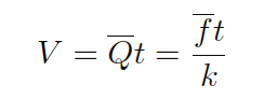
If pickup signal frequency directly represents volumetric flow rate, then the total number of pulses accumulated in any given time span will represent the amount of fluid volume (V ) passed through the turbine meter over that same time span.
We may express this algebraically as the product of average flow rate (Q), average frequency (f), k factor, and time:
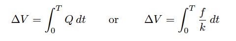
A more sophisticated way of calculating total volume passed through a turbine meter requires calculus, representing change in volume as the time-integral of instantaneous signal frequency and k factor over a period of time from t = 0 to t = T:
We may achieve approximately the same result simply by using a digital counter circuit to totalize pulses output by the pickup coil and a microprocessor to calculate volume in whatever unit of measurement we deem appropriate.
As with the orifice plate flow element, standards have been drafted for the use of turbine flowmeters as precision measuring instruments in gas flow applications, particularly the custody transfer of natural gas.
The American Gas Association has published a standard called the Report #7 specifying the installation of turbine flow meters for high-accuracy gas flow measurement, along with the associated mathematics for precisely calculating flow rate based on turbine speed, gas pressure, and gas temperature.
Pressure and temperature compensation is relevant to turbine flow meters in gas flow applications because the density of the gas is a strong function of both pressure and temperature.
The turbine wheel itself only senses gas velocity, and so these other factors must be taken into consideration to accurately calculate mass flow (or standard volumetric flow; e.g. SCFM).
In high-accuracy applications, it is important to individually determine the k factor for a turbine flow meter’s calibration. Manufacturing variations from flow meter to flow meter make precise duplication of k factor challenging, and so a flow meter destined for high-accuracy measurement should be tested against a “flow prover” in a calibration laboratory to empirically determine its k factor.
If possible, the best way to test the flow meter’s k factor is to connect the prover to the meter on site where it will be used. This way, the any effects due to the piping before and after the flowmeter will be incorporated in the measured k factor.
Advantages Turbine Flowmeter
The cost is moderate.
Very good at clean,
Low viscosity fluids of moderate velocity and a steady rate.
Turn down is very good as it can read very low compared to the maximum flow.
They are reliable if put in a clean fluid especially if it has some lubricity.
AGA and API approved for custody transfers.
Wide flow rangeability including low flow rates
Turndown ratio is up to 35:1
Good level of accuracy at an economic price
Simple, durable construction
Easy to install and maintain
Flexible connection to flow instruments for flow control
Wide variety of process connections
Turbine meters can operate over a wide range of temperatures and pressures
Low pressure drop across the turbine
Provides a convenient signal output
Disadvantages Turbine Flowmeter
They do cause some pressure drop where that may be a factor such as gravity flows.
Not reliable for steam.
Bearings wear out problem.
Requires constant backpressure to prevent cavitation
Accuracy adversely affected by bubbles in liquids
Turbine meters can be used with clean liquids and gases only (may need to install a strainer upstream to prevent damage from particulates)
Not applicable for measuring corrosive fluids
Requires a turbulent flow profile (consistent fluid velocity across the pipe diameter) for accuracy
Sensitive to changes in fluid viscosity
Require a straight run of pipe before and after the turbine meter to allow swirl patterns in the flow stream to dissipate
May not function properly with high viscosity fluids where the flow profile is laminar
Applications
In order of magnitude from largest to smallest,
These are used in oil and gas,
Water and waste water,
Gas utility,
Chemical,
Power, food and beverage
Aerospace
Pharmaceutical,
Metals and mining
Pulp and paper.
Cautions for Turbine Flow meters
Turbine meters are less accurate at low flow rates due to rotor/bearing drag that slows the rotor. Make sure to operate these flow meters above approximately 5 percent of maximum flow.
Turbine flow meters should not be operated at high velocity because premature bearing wear and/or damage can occur.
Be careful when measuring fluids that are non-lubricating because bearing wear can cause the flow meter become inaccurate and fail.
In some applications, bearing replacement may need to be performed routinely and increase maintenance costs.
Application in dirty fluids should generally be avoided so as to reduce the possibility of flow meter wear and bearing damage.
In summary, turbine flow meters have moving parts that are subject to degradation with time and use.
Abrupt transitions from gas flow to liquid flow should be avoided because they can mechanically stress the flow meter, degrade accuracy, and/or damage the flow meter.
These conditions generally occur when filling the pipe and under slug flow conditions. Two-phase flow conditions can also cause turbine flow meters to measure inaccurately.
Turbine Flow Meter Installation Procedure
Turbine flow meters are designed with wear resistant internal components to provide trouble-free operation and a long service life.
Fluid entering the flow meter is first conditioned by the inlet flow straightener which reduces turbulence in the fluid.
The moving fluid causes the rotor to spin at a speed that is proportional to its flow rate.
As the blades on the rotor pass through the magnetic field of the pickup, an electronic pulse is generated.
This pulse train signal can then be used to monitor the fluids actual flow rate or the total amount of fluid that has passed through the flow meter.
The number of electronic pulses generated by the meter, per unit volume, is known as its K-Factor. Each flow meter is calibrated to find its unique K-Factor, which is supplied with the flow meter when purchased.
[ads id="ads1"]
Installation Procedure
Before installation, the flow meter should be checked for foreign material and to ensure that the rotor spins freely.
All upstream fluid lines should also be cleared of any debris. Also, make sure that fluid flow has been shut off and all pressure in the lines has been released prior to installing the flow meter into an existing system.
The flow meter must be installed with the flow direction arrow pointing in the direction of fluid flow. The flow direction arrow can be found on the side of the flow meter.
The flow meter is designed to work in any orientation, but the preferred orientation is to have the meter installed in horizontal piping.
The fluid to be measured is recommended to be filtered. The best location for the filter or strainer would be upstream of the flow meter, after any other system components, while maintaining straight piping requirements.

The preferred plumbing setup is one containing a bypass line (above figure). This allows meter inspection and repair without interrupting flow, as well as the ability to cycle the fluid through the system filter before diverting to the flow meter.
If a bypass line is not used, it is important that all flow control valves be located downstream of the flow meter (below figure).

Start-Up Procedure
- After meter installation, close the isolation valves and open the bypass valve. Flow liquid through the system for a sufficient time to eliminate any air or gas in the flow line.
- Slowly open the upstream isolating valve to fill the flow meter with liquid.
- Open the downstream isolating valve to start fluid flow through the flow meter, permitting the flow meter to start to operate, then close the bypass valve completely.
- If the downstream valve is used as a flow control valve, adjust the valve to provide the required flow rate through the flow meter.
Operation Limitations
Turbine Flowmeter Troubleshooting Guide


Turbine Flow Meter Calibration
A turbine meter consists of a practically friction-free rotor pivoted along the axis of the meter tube and designed in such a way that the rate of rotation of the rotor is proportional to the rate of flow of fluid through the meter. This rotational speed is sensed by means of an electric pick-off coil fitted to the outside of the meter housing.
The only moving component in the meter is the rotor, and the only component subject to wear is the rotor bearing assembly. However, with careful choice of materials (e.g., tungsten carbide for bearings) the meter should be capable of operating for up to five years without failure.
There are several characteristics of turbine flow meters that make them an excellent choice for some applications. The flow sensing element is very compact and light weight compared to various other technologies. This can be advantageous in applications where space is a premium
Turbine Flow Meter

Primary Vs. Secondary Standards
A primary standard calibration is one that is based on measurements of natural physical parameters (i.e., mass, distance, and time). This calibration procedure assures the best possible precision error, and through traceability, minimizes bias or systematic error.
A secondary standard calibration is not based on natural, physical measurements. It often involves calibrating the user’s flow meter against another flow meter, known as a “master meter,” that has been calibrated itself on a primary standard.
[ads id="ads1"]
Calibration
“To calibrate” means “to standardize (as a measuring instrument) by determining the deviation from a standard so as to determine the proper correction factors.” There are two key elements to this definition: determining the deviation from a standard, and ascertaining the proper correction factors.
Flow meters need periodic calibration. This can be done by using another calibrated meter as a reference or by using a known flow rate. Accuracy can vary over the range of the instrument and with temperature and specific weight changes in the fluid, which may all have to be taken into account.
Thus, the meter should be calibrated over temperature as well as range, so that the appropriate corrections can be made to the readings. A turbine meter should be calibrated at the same kinematic viscosity at which it will be operated in service. This is true for fluid states, liquid and gas.

Master Meter
A master meter is a flow meter that has been calibrated to a very high degree of accuracy. Types of flow meters used as master meters include turbine meters, positive displacement meters, venturi meters, and Coriolis meters.
The meter to be calibrated and the master meter are connected in series and are therefore subject to the same flow regime. To ensure consistent accurate calibration, the master meter itself must be subject to periodic re-calibration
Gravimetric Method
This is the weight method, where the flow of liquid through the meter being calibrated is diverted into a vessel that can be weighed either continuously or after a predetermined time.
The weight is usually measured with the help of load cells. The weight of the liquid is then compared with the registered reading of the flow meter being calibrated
Volumetric Method
In this technique, flow of liquid through the meter being calibrated is diverted into a tank of known volume. The time to displace the known volume is recorded to get the volumetric flow rate eg:- gallons per minute. This flow rate can then be compared to the turbine flow meter readings
K-Factor
“K” is a letter used to denote the pulses per gallon factor of a flow meter.
Repeatability
The maximum deviation from the corresponding data points taken from repeated tests under identical conditions.
Flow Transfer Standards
Unlike primary flow standards, whose most important characteristics are their traceability to primary physical measurements (resulting in the minimization of absolute uncertainties, with less concern for usability or cost issues), the key criteria for secondary Flow Transfer Standards are portability, low cost and the ability to calibrate the flow meter in the physical piping configuration it lives in.
Instead of removing flowmeters from service for re-calibration, FTS devices allow users to “bring the calibrator to the flow meter.” These portable, documenting field flow calibrators are intended for in-line calibration and validation of meters using the actual process conditions for gas or liquid.
Advanced FTS systems in corporate hand-held electronics with built-in signal conditioners, thus eliminating bulky interface boxes and the need to carry a laptop computer into the field.
High-quality Flow Transfer Standards also have the capability of measuring and correcting the influences of line pressure and temperature effects on flow.
Operation of a portable Flow Transfer Standard requires that a master meter be installed in series with the flow meter under test. The readings from these instruments are compared at various flow rates or flow totals.
A technician can install the master meter in the same system as the test meter, perform the calibration, and note any changes in performance.
New calibration data might cause re-scaling or new data points to be programmed into a flow meter’s computer to align the measurement with the current flow calibration data.
[ads id="ads1"]
Typical Calibration Techniques
Most flow meter calibration service suppliers provide a choice of calibration techniques to accommodate different applications and flow measurement requirements.
One of the most common techniques is the single-viscosity calibration, which consists of running 10 evenly spaced calibration points at a specified liquid viscosity.
Single-viscosity calibrations are recommended when the viscosity of the liquid being measured is constant. If a higher degree of accuracy is needed, again, the more data points taken the better defined the meter calibration curve will be.

Strouhal Number/Roshko Number
The best, and only completely correct way to present the data for a Turbine Meter is Strouhal Number as a function of Roshko Number, i.e., through the use of two dimensionless parameters.
The St vs. Ro presentation takes into account all of the secondary effects to which the meter is sensitive.
This presentation or correlation is correct for both liquids and gases. It is almost a must for gas calibrations since the density and kinematic viscosity are a function of both temperature and pressure
[ads id="ads1"]
Your Calibrated Flowmeter
Once your flow meter is calibrated, it may still read exactly the same under the same flow conditions as it did before it was calibrated.
The difference is that you will know exactly how close those values are to the true values, and you will have a formula to use to calculate the true values from the actual values read by your flow meter.
You can have a correction factor obtained from calibration which you can apply to the flow meter readings to obtain the correct or true flow meter readings.
K-factor ignores the effects of changing temperature on the meter body since the meter will change diameter when the temperature changes.
The use of Strouhal Number instead of simple K-Factor will account for this temperature effect.
A turbine meter consists of a practically friction-free rotor pivoted along the axis of the meter tube and designed in such a way that the rate of rotation of the rotor is proportional to the rate of flow of fluid through the meter. This rotational speed is sensed by means of an electric pick-off coil fitted to the outside of the meter housing.
The only moving component in the meter is the rotor, and the only component subject to wear is the rotor bearing assembly. However, with careful choice of materials (e.g., tungsten carbide for bearings) the meter should be capable of operating for up to five years without failure.
There are several characteristics of turbine flow meters that make them an excellent choice for some applications. The flow sensing element is very compact and light weight compared to various other technologies. This can be advantageous in applications where space is a premium
Turbine Flow Meter
Primary Vs. Secondary Standards
A primary standard calibration is one that is based on measurements of natural physical parameters (i.e., mass, distance, and time). This calibration procedure assures the best possible precision error, and through traceability, minimizes bias or systematic error.
A secondary standard calibration is not based on natural, physical measurements. It often involves calibrating the user’s flow meter against another flow meter, known as a “master meter,” that has been calibrated itself on a primary standard.
[ads id="ads1"]
Calibration
“To calibrate” means “to standardize (as a measuring instrument) by determining the deviation from a standard so as to determine the proper correction factors.” There are two key elements to this definition: determining the deviation from a standard, and ascertaining the proper correction factors.
Flow meters need periodic calibration. This can be done by using another calibrated meter as a reference or by using a known flow rate. Accuracy can vary over the range of the instrument and with temperature and specific weight changes in the fluid, which may all have to be taken into account.
Thus, the meter should be calibrated over temperature as well as range, so that the appropriate corrections can be made to the readings. A turbine meter should be calibrated at the same kinematic viscosity at which it will be operated in service. This is true for fluid states, liquid and gas.
Master Meter
A master meter is a flow meter that has been calibrated to a very high degree of accuracy. Types of flow meters used as master meters include turbine meters, positive displacement meters, venturi meters, and Coriolis meters.
The meter to be calibrated and the master meter are connected in series and are therefore subject to the same flow regime. To ensure consistent accurate calibration, the master meter itself must be subject to periodic re-calibration
Gravimetric Method
This is the weight method, where the flow of liquid through the meter being calibrated is diverted into a vessel that can be weighed either continuously or after a predetermined time.
The weight is usually measured with the help of load cells. The weight of the liquid is then compared with the registered reading of the flow meter being calibrated
Volumetric Method
In this technique, flow of liquid through the meter being calibrated is diverted into a tank of known volume. The time to displace the known volume is recorded to get the volumetric flow rate eg:- gallons per minute. This flow rate can then be compared to the turbine flow meter readings
K-Factor
“K” is a letter used to denote the pulses per gallon factor of a flow meter.
Repeatability
The maximum deviation from the corresponding data points taken from repeated tests under identical conditions.
Flow Transfer Standards
Unlike primary flow standards, whose most important characteristics are their traceability to primary physical measurements (resulting in the minimization of absolute uncertainties, with less concern for usability or cost issues), the key criteria for secondary Flow Transfer Standards are portability, low cost and the ability to calibrate the flow meter in the physical piping configuration it lives in.
Instead of removing flowmeters from service for re-calibration, FTS devices allow users to “bring the calibrator to the flow meter.” These portable, documenting field flow calibrators are intended for in-line calibration and validation of meters using the actual process conditions for gas or liquid.
Advanced FTS systems in corporate hand-held electronics with built-in signal conditioners, thus eliminating bulky interface boxes and the need to carry a laptop computer into the field.
High-quality Flow Transfer Standards also have the capability of measuring and correcting the influences of line pressure and temperature effects on flow.
Operation of a portable Flow Transfer Standard requires that a master meter be installed in series with the flow meter under test. The readings from these instruments are compared at various flow rates or flow totals.
A technician can install the master meter in the same system as the test meter, perform the calibration, and note any changes in performance.
New calibration data might cause re-scaling or new data points to be programmed into a flow meter’s computer to align the measurement with the current flow calibration data.
[ads id="ads1"]
Typical Calibration Techniques
Most flow meter calibration service suppliers provide a choice of calibration techniques to accommodate different applications and flow measurement requirements.
One of the most common techniques is the single-viscosity calibration, which consists of running 10 evenly spaced calibration points at a specified liquid viscosity.
Single-viscosity calibrations are recommended when the viscosity of the liquid being measured is constant. If a higher degree of accuracy is needed, again, the more data points taken the better defined the meter calibration curve will be.
Strouhal Number/Roshko Number
The best, and only completely correct way to present the data for a Turbine Meter is Strouhal Number as a function of Roshko Number, i.e., through the use of two dimensionless parameters.
The St vs. Ro presentation takes into account all of the secondary effects to which the meter is sensitive.
This presentation or correlation is correct for both liquids and gases. It is almost a must for gas calibrations since the density and kinematic viscosity are a function of both temperature and pressure
[ads id="ads1"]
Your Calibrated Flowmeter
Once your flow meter is calibrated, it may still read exactly the same under the same flow conditions as it did before it was calibrated.
The difference is that you will know exactly how close those values are to the true values, and you will have a formula to use to calculate the true values from the actual values read by your flow meter.
You can have a correction factor obtained from calibration which you can apply to the flow meter readings to obtain the correct or true flow meter readings.
K-factor ignores the effects of changing temperature on the meter body since the meter will change diameter when the temperature changes.
The use of Strouhal Number instead of simple K-Factor will account for this temperature effect.
Turbine Flow Meter Verification
Question :
” We have a turbine flow meter, gas chromotograph & flow computer installed at our site, similar units installed at GAIL terminal also. How metering can be done with these two setups. GAIL (gas distribution company) people used to do turbine flow meter calibration, is it possible to do calibration on site for a turbine type flow meter. Please let me know the procedure if any.”
Answer :
Turbine Flow Meter Verification
No calibration is done on a Turbine flow meter. The meter can only verified or proved against a standard reference measurement
Meter proving is a physical test used to determine the accuracy and performance of the meters
The turbine meter can be proved by placing the meter in series with a meter prover which has a known or base volume in such a way that the fluid measured by the meter is also measured by the prover.

Regardless of the prover or meter type, the basic proving principle is as follows

The above needs to be updated in the Flow computer. Gas chromatograph will provide the online gas composition which can be used to calculate the molecular weight and Specific gravity of the fluid being measured.
[ads id="ads1"]
Basic diagram of a meter proving is described as below:

For more information, kindly refer to compact provers from Emerson and API chapter 4 which covers the proving of meters.
1. What is a turbine flow meter? How and when is it used?
A turbine flow meter is a liquid/gas velocity measurement device.
The turbine flow meter contains a free spinning turbine rotor that turns at a speed that is proportional to the flow velocity.
2. Can liquid meters measure gas and vice versa?
No – gas in a liquid meter will cause the meter to read high and can cause catastrophic failures.
Liquid going through a gas meter will cause erroneous indications of the gas flow rate and can cause meter damage.
3. How do you size gas turbines?
With gas turbines, flowing pressure and temperature are taken into account, as well as the flow rate.
4. What is the maximum working pressure?
The maximum working pressure of meters is determined by the end connections.
5. What size meter will I need for a certain size pipe?
Meter size depends on the flow rate being metered, not pipe size. Most oilfield applications oversize the pipe so the meter flow rate size may be smaller than the pipe size.
If the fluid being measured is a non-lubricating liquid, such as solvent, gasoline, acetone, alcohol, etc., the meter must be run in the upper 60% of the operating range.
6. What happens when flow goes in the reverse direction in the meter?
The meter is not damaged as the meters are designed to be Bi-Directional, but the counter will read the total of the forward flow and the reverse flow.
For example, if five barrels flow through the meter in the forward direction, and then four barrels flow back through the meter in the reverse direction, the counter will show nine barrels even though the net transfer through the meter is only one barrel.
7. How do you size meters for certain applications?
Injection wells – flow rates, working pressure and end connections.
Separators – recommend snap dumps. (You need the instantaneous flow rate when it is dumping, not the total amount dumped per day.)
Oil meters – consider viscosity of oil and gas in the fluid. Install a back-pressure device downstream of the meter that will keep the gas entrained in the fluid.
Meters in general – try to mid-range if possible.
Meters for CO2 service – recommend upper 60% range. Measure it in the liquid state only
8. What happens to accuracy when you are above or below range of the meter?
The bottom end of the flow range is the critical point. Below this minimum, the factor changes with flow rate change. Each meter performs differently, so it is not possible to predict the performance.
The top end of the flow range is based more on bearing wear than accuracy.
The meter will still be accurate above the top end of the range, but the kit will not last long if continuously run above the top end of the flow range.
Over range use should be limited to 10% of the maximum flow rate, and not more than 10% of the time.
9. What is the difference between dump rate and production rate?
Production rate: how much the well makes in a day Dump rate: the instantaneous flow rate.
10. What is the life expectancy of the meter?
Many factors can affect this, but, normally, if debris is kept out of the meter and fine particles such as sand are kept to a minimum, the meter can last for many years.
Life expectancy depends entirely on the application and meter size.
11. Is the turbine meter easy to work on and maintain?
Yes – minimal tools are required
12. How long will the rotor and vane of meter last?
The longevity of the rotor and vane kit depends strictly on the application. A meter that is measuring a clean lubricating fluid will last longer than one that is measuring a dirty, sandy, non-lubricating product.
The life of the meter depends on the application and meter size.
13. Can the meter be used with propane, butane, CO2, etc.?
Yes – the product must be liquid, and because it is less lubricating, it is best used in the upper 60% range of the meter.
Precautions must be exercised to prevent gas flashing, which can cause catastrophic failures and/or high readings.
14. Can meters be used with piston type pumps?
The turbine meter works well in this application compared to other measurement devices. However, due to the constant pulsation of the fluid, the meter may be the best choice because of its design.
Depending on the back-pressure and the proximity of the installed meter to the pump, the snap rings can wear, and loss of one vane and the rotor can occur. If the turbine meter is some distance away from the triplex pump, the standard meter will most likely give adequate performance.
Question :
” We have a turbine flow meter, gas chromotograph & flow computer installed at our site, similar units installed at GAIL terminal also. How metering can be done with these two setups. GAIL (gas distribution company) people used to do turbine flow meter calibration, is it possible to do calibration on site for a turbine type flow meter. Please let me know the procedure if any.”
Answer :
Turbine Flow Meter Verification
No calibration is done on a Turbine flow meter. The meter can only verified or proved against a standard reference measurement
Meter proving is a physical test used to determine the accuracy and performance of the meters
The turbine meter can be proved by placing the meter in series with a meter prover which has a known or base volume in such a way that the fluid measured by the meter is also measured by the prover.

Regardless of the prover or meter type, the basic proving principle is as follows
The above needs to be updated in the Flow computer. Gas chromatograph will provide the online gas composition which can be used to calculate the molecular weight and Specific gravity of the fluid being measured.
[ads id="ads1"]
Basic diagram of a meter proving is described as below:

For more information, kindly refer to compact provers from Emerson and API chapter 4 which covers the proving of meters.
1. What is a turbine flow meter? How and when is it used?
A turbine flow meter is a liquid/gas velocity measurement device.
The turbine flow meter contains a free spinning turbine rotor that turns at a speed that is proportional to the flow velocity.
2. Can liquid meters measure gas and vice versa?
No – gas in a liquid meter will cause the meter to read high and can cause catastrophic failures.
Liquid going through a gas meter will cause erroneous indications of the gas flow rate and can cause meter damage.
3. How do you size gas turbines?
With gas turbines, flowing pressure and temperature are taken into account, as well as the flow rate.
4. What is the maximum working pressure?
The maximum working pressure of meters is determined by the end connections.
5. What size meter will I need for a certain size pipe?
Meter size depends on the flow rate being metered, not pipe size. Most oilfield applications oversize the pipe so the meter flow rate size may be smaller than the pipe size.
If the fluid being measured is a non-lubricating liquid, such as solvent, gasoline, acetone, alcohol, etc., the meter must be run in the upper 60% of the operating range.
6. What happens when flow goes in the reverse direction in the meter?
The meter is not damaged as the meters are designed to be Bi-Directional, but the counter will read the total of the forward flow and the reverse flow.
For example, if five barrels flow through the meter in the forward direction, and then four barrels flow back through the meter in the reverse direction, the counter will show nine barrels even though the net transfer through the meter is only one barrel.
7. How do you size meters for certain applications?
Injection wells – flow rates, working pressure and end connections.
Separators – recommend snap dumps. (You need the instantaneous flow rate when it is dumping, not the total amount dumped per day.)
Oil meters – consider viscosity of oil and gas in the fluid. Install a back-pressure device downstream of the meter that will keep the gas entrained in the fluid.
Meters in general – try to mid-range if possible.
Meters for CO2 service – recommend upper 60% range. Measure it in the liquid state only
8. What happens to accuracy when you are above or below range of the meter?
The bottom end of the flow range is the critical point. Below this minimum, the factor changes with flow rate change. Each meter performs differently, so it is not possible to predict the performance.
The top end of the flow range is based more on bearing wear than accuracy.
The meter will still be accurate above the top end of the range, but the kit will not last long if continuously run above the top end of the flow range.
Over range use should be limited to 10% of the maximum flow rate, and not more than 10% of the time.
9. What is the difference between dump rate and production rate?
Production rate: how much the well makes in a day Dump rate: the instantaneous flow rate.
10. What is the life expectancy of the meter?
Many factors can affect this, but, normally, if debris is kept out of the meter and fine particles such as sand are kept to a minimum, the meter can last for many years.
Life expectancy depends entirely on the application and meter size.
11. Is the turbine meter easy to work on and maintain?
Yes – minimal tools are required
12. How long will the rotor and vane of meter last?
The longevity of the rotor and vane kit depends strictly on the application. A meter that is measuring a clean lubricating fluid will last longer than one that is measuring a dirty, sandy, non-lubricating product.
The life of the meter depends on the application and meter size.
13. Can the meter be used with propane, butane, CO2, etc.?
Yes – the product must be liquid, and because it is less lubricating, it is best used in the upper 60% range of the meter.
Precautions must be exercised to prevent gas flashing, which can cause catastrophic failures and/or high readings.
14. Can meters be used with piston type pumps?
The turbine meter works well in this application compared to other measurement devices. However, due to the constant pulsation of the fluid, the meter may be the best choice because of its design.
Depending on the back-pressure and the proximity of the installed meter to the pump, the snap rings can wear, and loss of one vane and the rotor can occur. If the turbine meter is some distance away from the triplex pump, the standard meter will most likely give adequate performance.
Calibration of Turbine Meters
1. What is a calibration factor and how is a meter calibrated? What happens if the calibration factor tag is lost?
The calibration factor is the number of pulses per gallon a meter will produce. Every meter is individually calibrated by flowing a known volume of water through the meter at five different flow rates – one at the maximum rate, one at the minimum rate, and three at rates equidistantly spaced between.
This calibration factor is put on a plastic tag and attached to the conduit pickup adapter of a meter.
Since kits are also calibrated individually and come with their own calibration factor, if the original kit has been changed and the new calibration factor tag is lost, the only way to get the actual factor is to send the meter to the vendor for re-calibration or a third party proving facility.
Sometimes a nominal factor will be close enough for the application.
If a meter requires repairs, it is critical to change the entire kit. Never replace or interchange parts.
2. What method is used to calibrate turbine flow meters and replacement rotor and vane kits?
The volumetric tank method is used. The volume of the calibration tanks is determined by filling them with water that is measured by tanks that are calibrated and certified by the National Institute of Standards and Technology.
These calibration tank volumes are checked periodically. Each flow meter and kit is placed in a flowline, and the calibration tank is filled at five different flow rates over the range of the meter.
One run is performed at the maximum rate, one at the minimum rate, and three runs are performed at rates equidistantly spaced between the maximum and minimum rates.
The total number of pulses generated by the flow meter at each flow rate is recorded. The total pulses are divided by the total volume at each flow rate to determine the calibration factor. The mean factor is determined as halfway between the high and low factors.
The flow meter is tagged with the mean factor. The maximum deviation between the mean factor and high or low factor cannot exceed ± 0.5% for industrial grade meters or ± 1.0% for standard grade meters.
Troubleshooting Tips
1. What is the most common problem with the meters?
Debris getting in the meter can cause readings to be high, low or non-existent. This problem can be solved with the use of a strainer or filters ahead of the meter.
These are recommended in all meter installations where debris or particles may be present in the flow stream.
2. What if the meter is not reading?
Check for debris that prevents the turbine from turning, or a bad pickup.
3. The meter reads low, and there is no debris in it.
Check for debris binding the turbine. Remove the meter internals to thoroughly observe, because some debris, such as Teflon tape, cannot be seen by just looking through the meter.
Check for damage to the rotor or shaft, bearing wear, external factors actually reducing flow such as a valve, a well pressuring up due to a blockage, an incorrect divisor, malfunctioning totalizer, or shaft broken on one side of rotor.
Debris can cause one of three problems:
No reading at all (turbine is not turning)
Low reading (debris is binding the turbine)
High reading (debris is jetting fluid through the turbine)
4. The rate seems to be increasing, but the pressure does not change.
Check for a buildup in the meter and upstream piping, such as scale, paraffin, etc.
5. What causes turbine flow meters to read high, more than actual flow?
Debris blocking part of the inlet to the meter
A partially closed valve or other restriction upstream of the meter
An elbow, tee or some other flow diverter too close to the upstream end of the meter viscosity of fluid being measured
Misalignment of the meter or gaskets in the flow line
Wax or scale buildup in the pipe or meter
An incorrect divisor
A malfunctioning totalizer.
A malfunctioning/faulty magnetic pickup.
Noise from vibration or nearby energy source emitting noise.
6. The meter has suddenly started reading very high.
Check for debris lodged on the upstream end of the turbine, or a change of fluid conditions that could cause gas breakout. Gas or air in the fluid can cause also high reading. A valve used for rate control must be mounted on the downstream side of the meter.
Back-flow is measured and added to the regular flow volume, causing the totalizer to yield excessively high values. A leaking check valve, therefore, can cause a high totalizer reading.
7. What problems will make a liquid meter read inaccurately?
Debris in the meter, a broken shaft, viscous fluids, gas in flow line and/or improper sizing or installation can cause inaccurate readings.
8. When should a rotor and vane kit be replaced due to bearing wear?
Bearing wear on a shaft will appear as a dimple in the end of the shaft or a groove cut around the shaft ends. When a groove is observed, the kit should be replaced.
As a rule of thumb, if a dimple covers 66% of the surface area of the end of the shaft, the kit should be replaced. If the groove on the side of the shaft can be felt, it should be replaced.
9. How do you check pickups?
The pickup can be checked with an ohmmeter, or it can be connected to a properly working readout device.
When a wire brush or screwdriver is passed across the pickup tip, the readout should show a rate or update of the total if the pickup is functioning properly