Basics of Ultrasonic Flow meters
The term ‘ultrasonic’ is used to describe pressure waves at frequencies higher than the human ears can detect.
The velocity of the sound waves in the fluid is the same as the velocity of sound in the fluid. If an ultrasonic beam is transmitted across a pipeline at an angle to the flow direction, the time taken for the pulse to reach the receiver is a function of the flow velocity of the fluid, as well as the velocity of sound in the fluid.
Ultrasonic Flow Meters Working Principle

- tAB is Time required for ultrasonic wave to travel from Sensor A to B sensor
- tBA is Time required for ultrasonic wave to travel from Sensor B to A sensor
This can be either in the direction of flow (downstream) or against the direction of flow (upstream). The time (transit) that the signal requires to arrive at the receiver is then measured.
According to physical principles, the signal sent against the direction of flow requires longer to return than the signal in the direction of flow.
The difference in the transit time is directly proportional to the velocity of flow.
v ≈ Δ t
v = k Δ t
w here k is a constant
Flow rate is thus,
Q = v •. A
where,
v = flow velocity
Δt = transit time difference between the signal in the direction of flow and against the direction of flow
Q = volumetric flow
A = pipe cross-sectional area
The mathematical relationship between fluid velocity (v) and the Doppler frequency shift (Δf) is as follows, for fluid velocities much less than the speed of sound through that fluid (v << c):
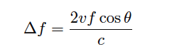
Where,
Δf = Doppler frequency shift
v = Velocity of fluid (actually, of the particle reflecting the sound wave)
f = Frequency of incident sound wave
θ = Angle between transducer and pipe centerlines
c = Speed of sound in the process fluid
Formulas Calculations check here

Transmitter and receiver roles are constantly switched by electronics. Ultrasonic pulses traveling in the direction of the flow, travel path between transducers in a shorter period of time than pulses traveling against the flow.
This is because the flow speeds up pulses traveling downstream but slows down pulses traveling upstream. The equation is;

Multiple traverse Ultrasonic Flow meter
A multiple-transverse configuration consists of two transducers mounted on the pipe so that the signal traverses the fluid two or more times before reaching the other transducer (figure 2). The walls of the pipe reflect the ultrasonic signal in order to maintain at 45 angle.
This allows the signal to remain in the fluid longer, increasing the effective length ( L ) of the signal path, and thus increasing accuracy.
The number of times the signal can traverse through the fluid depends on factors such as transducer frequency, pipe size, pipe wall condition, and the fluid being measured.

Features:
- Easy to carry;
- Low maintenance;
- Can only be used to measure cleaning liquids;
- Not subject to pipe diameter restrictions;
- No flow obstruction measurement, no additional pressure loss.
Types of Ultrasonic Flow Meter
Factors Affecting Performance and Accuracy
Pros and Cons of Ultrasonic Flow Meters

Advantages of Ultrasonic Flow Meter
The advantages are
It does not block the path of liquid flow.
The o/p of this meter is different for density, viscosity & temperature of the liquid.
The flow of liquid is bidirectional
The dynamic response of this meter is good.
The output of this meter is in analog form
Conservation of energy
It is appropriate for huge quality flow measurement
It is handy to fit and maintain
Versatility is good
There is no contact to liquid
There is no leakage risk
There are no moving parts, pressure loss
High accuracy
Disadvantages of Ultrasonic Flow Meter
The disadvantages are
It is expensive as compared with other mechanical flow meters.
Design of this meter is complex
Auditory parts of this meter are expensive.
These meters are complicated as compared with other meters, thus it requires specialists for maintaining and repairing these meters
It cannot measure cement or concrete pipes one they rusted.
It doesn’t work once the pipe contains holes or bubbles in it
Can’t measure cement/concrete pipe or pipe with such material lining
Applications
The applications of ultrasonic flow meters include the following.
These meters are used in wastewater and dirty liquid applications
These meters are used wherever chemical compatibility, less maintenance, and low-pressure drop are required.
These meters are used to measure the velocity of a liquid through ultrasound to analyze volume flow.
These meters measure the disparity between the transit time of ultrasonic pulses which transmits with the direction of liquid flow
The applications of these meters range from process to custody flow
This is one kind of device for volumetric flow measurement for liquids as well as gases.
These are excellent alternatives for both vortex & electromagnetic flowmeters.
The difference in the transit time is directly proportional to the velocity of flow.
v ≈ Δ t
v = k Δ t
w here k is a constant
Flow rate is thus,
Q = v •. A
where,
v = flow velocity
Δt = transit time difference between the signal in the direction of flow and against the direction of flow
Q = volumetric flow
A = pipe cross-sectional area
The mathematical relationship between fluid velocity (v) and the Doppler frequency shift (Δf) is as follows, for fluid velocities much less than the speed of sound through that fluid (v << c):
Where,
Δf = Doppler frequency shift
v = Velocity of fluid (actually, of the particle reflecting the sound wave)
f = Frequency of incident sound wave
θ = Angle between transducer and pipe centerlines
c = Speed of sound in the process fluid
Note how the Doppler effect yields a direct measurement of fluid velocity from each echo received by the transducer.
This stands in marked contrast to measurements of distance based on time-off light (time domain reflectometry – where the amount of time between the incident pulse and the returned echo is proportional to distance between the transducer and the reflecting surface)
such as in the application of ultrasonic liquid level measurement. In a Doppler flowmeter, the time delay between the incident and reflected pulses is irrelevant. Only the frequency shift between the incident and reflected signals matters.
This frequency shift is also directly proportional to the velocity of flow, making the Doppler ultrasonic flowmeter a linear measurement device.
Re-arranging the Doppler frequency shift equation to solve for velocity (again, assuming v << c)
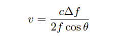
Knowing that volumetric flow rate is equal to the product of pipe area and the average velocity of the fluid (Q = Av), we may re-write the equation to directly solve for calculated flow rate (Q):
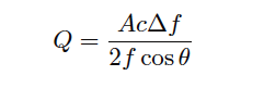
A very important consideration for Doppler ultrasonic flow measurement is that the calibration of the flow meter varies with the speed of sound through the fluid (c).
This is readily apparent by the presence of c in the above equation: as c increases, Δf must proportionately decrease for any fixed volumetric flow rate Q.
Since the flowmeter is designed to directly interpret flow rate in terms of Δf, an increase in c causing a decrease in Δf will thus register as a decrease in Q.
This means the speed of sound for a fluid must be precisely known in order for a Doppler ultrasonic flowmeter to accurately measure flow.
The speed of sound through any fluid is a function of that medium’s density and bulk modulus (how easily it compresses):
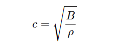
Where,
c = speed of sound in a material (meters per second)
B = Bulk modulus (pascals, or newtons per square meter)
ρ = Mass density of fluid (kilograms per cubic meter)
Temperature affects liquid density, and composition (the chemical constituency of the liquid) affects bulk modulus. Thus, temperature and composition both are influencing factors for Doppler ultrasonic flowmeter calibration.
Pressure is not a concern here, since pressure only affects the density of gases, and we already know Doppler flowmeters only function with liquids.
Following on the theme of requiring bubbles or particles of sufficient size, another limitation of Doppler ultrasonic flowmeters is their inability to measure flow rates of liquids that are too clean and too homogeneous. In such applications, the sound-wave reflections will be too weak to reliably measure.
Such is also the case when the solid particles have a speed of sound too close to the that of the liquid, since reflection happens only when a sound wave encounters a material with a markedly different speed of sound.
Doppler-type ultrasonic flowmeters are useless in applications where we cannot obtain strong sound-wave reflections.
Transit-time flowmeters, sometimes called counterpropagation flowmeters, are an alternative to Doppler ultrasonic flowmeters.
A transit-time ultrasonic flowmeter uses a pair of opposed sensors to measure the time difference between a sound pulse traveling with the fluid flow versus a sound pulse traveling against the fluid flow.
Since the motion of fluid tends to carry a sound wave along, the sound pulse transmitted downstream will make the journey faster than a sound pulse transmitted upstream:
Transit-time flow meters
The rate of volumetric flow through a transit-time flowmeter is a simple function of the upstream and downstream propagation times:
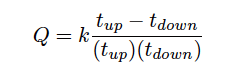
Where,
Q = Calculated volumetric flow rate
k = Constant of proportionality
tup = Time for sound pulse to travel from downstream location to upstream location (upstream, against the flow)
tdown = Time for sound pulse to travel from upstream location to downstream location (downstream, with the flow)
An interesting characteristic of transit-time velocity measurement is that the ratio of transit time difference over transit time product remains constant with changes in the speed of sound through the fluid.
If you would like to prove this to yourself, you may do so by substituting path length (L), fluid velocity (v), and sound velocity (c) for the times in the flow formula. Use tup = L/(c−v) and tdown = L/(c+v) as your substitutions, then algebraically reduce the flow formula until you find that all the c terms cancel. Your final result should be Q = 2kv/L .
When this equation is cast into terms of path length (L), fluid velocity (v), and sound velocity (c), the equation simplifies to Q = 2kv/L , proving that the transit-time flow meter is linear just like the Doppler flowmeter, with the advantage of being immune to changes in the fluid’s speed of sound.
Changes in bulk modulus resulting from changes in fluid composition, or changes in density resulting from compositional, temperature, or pressure variations therefore have little effect on a transit-time flow meter’s accuracy.
Not only are transit-time ultrasonic flow meters immune to changes in the speed of sound, but they are also able to measure that sonic velocity independent of the flow rate.
The equation for calculating speed of sound based on upstream and downstream propagation times is as follows:
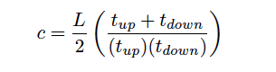
Where,
c = Calculated speed of sound in fluid
L = Path length
tup = Time for sound pulse to travel from downstream location to upstream location (upstream, against the flow)
tdown = Time for sound pulse to travel from upstream location to downstream location (downstream, with the flow)
While not necessary or even particularly relevant for the direct purpose of flow measurement, this inference of the fluid’s speed of sound is nevertheless useful as a diagnostic tool. If the true speed of sound for the fluid is known either by direct laboratory measurement of a sample or by chemical analysis of a sample, this speed may be compared against the flow meter’s reported speed of sound to check the flow meter’s absolute transit time measurement accuracy. Certain problems within the sensors or within the sensor electronics may be detected in this way.
A requirement for reliable operation of a transit-time ultrasonic flow meter is that the process fluid be free from gas bubbles or solid particles which might scatter or obstruct the sound waves.
Note that this is precisely the opposite requirement of Doppler ultrasonic flow meters, which require bubbles or particles to reflect sound waves.
These opposing requirements neatly distinguish applications suitable for transit-time flow meters from applications suitable for Doppler flow meters, and also raise the possibility of using transit-time ultrasonic flow meters on gas flow streams as well as on liquid flow streams.
One potential problem with any ultrasonic flow meter is being able to measure the true average fluid velocity when the flow profile changes with Reynolds number. If just one ultrasonic “beam” is used to probe the fluid velocity, the path this beam takes will likely see a different velocity profile as the flow rate changes (and the Reynolds number changes along with it).
Recall the difference in fluid velocity profiles between low Reynolds number flows (left) and high Reynolds number flows (right):

A popular way to mitigate this problem is to use multiple sensor pairs, sending acoustic signals along multiple paths through the fluid (i.e. a multipath ultrasonic flowmeter), and to average the resulting velocity measurements.
Dual-beam transit-time flow meters have been in use for well over a decade at the time of this writing (2009), and one manufacturer even has a five beam ultrasonic flowmeter model which they claim maintains an accuracy of ± 0.15% through the laminar-to-turbulent flow regime transition.
4 Channel ultrasonic flow meter
A simplified illustration of a Daniel four-beam (or four “chord”) ultrasonic flowmeter is shown here:
