Resistance Temperature Detectors (RTDs) rely on the predictable and repeatable phenomena of the electrical resistance of metals changing with temperature.
The temperature coefficient for all pure metals is of the same order – 0.003 to 0.007 ohms/ohm/°C. The most common metals used for temperature sensing are platinum, nickel, copper and molybdenum.
While the resistance – temperature characteristics of certain semiconductor and ceramic materials are used for temperature sensing, such sensors are generally not classified as RTDs.
How are RTDs constructed?
RTDs are manufactured in two ways: using wire or film. Wire RTDs are a stretched coil of fine wire placed in a ceramic tube that supports and protects the wire.
The wire may be bonded to the ceramic using a glaze. The wire types are generally the more accurate, due to the tighter control over metal purity and less strain related errors. They are also more expensive.
Film RTDs consist of a thin metal film that is silk-screened or vacuum spluttered onto a ceramic or glassy substrate. A laser trimmer then trims the RTD to its correct resistance value.
Film sensors are less accurate than wire types, but they are relatively inexpensive, they are available in small sizes and they are more robust.
Film RTDs can also function as a strain gauge – so don’t strain them! The alumina element should be supported by grease or a light elastomer, but never embedded in epoxy or mechanically clamped between hard surfaces.
RTDs cannot generally be used in their basic sensing element form, as they are too delicate. They are usually built into some type of assembly, which will enable them to withstand the various environmental conditions to which they will be exposed when used.
Most commonly this is a stainless steel tube with a heat conducting grease (that also dampens vibration). Standard tube diameters include 3, 4.5, 6, 8, 10, 12 and 15 mm and standard tube lengths include 250, 300, 500, 750 and 1000 mm.
Characteristics of RTDs
Metal RTDs have a response defined by a polynomial:
R(t) = R0 ( 1 + a.t + b.t2 + c.t3 )
Where R0 is the resistance at 0°C, “t” in the temperature in Celsius, and “a”, “b” and “c” are constants dependent on the characteristics of the metal. In practice this equation is a close but not perfect fit for most RTDs, so slight modifications are often be made.
Commonly, the temperature characteristics of an RTD are specified as a single number (the “alpha”), representing the average temperature coefficient over the 0 to 100°C temperature range as calculated by:
alpha = ( R100 – R0 ) / 100 . R0 in ohms/ohm/°C
Note: RTDs cover a sufficient temperature range that their response needs to be calibrated in terms of the latest temperature scale ITS90. For assistance with such calculations, see the RTD temperature calculator.
It is also of interest to note that the temperature coefficient of an alloy is frequently very different from that of the constituent metals. Small traces of impurities can greatly change the temperature coefficients.
Sometimes trace “impurities” are deliberately added so as to swamp the effects of undesired impurities which are uneconomic to remove. Other alloys can be tailored for particular temperature characteristics.
For example, an alloy of 84% copper, 12% Manganese and 4% Nickel has the property of having an almost zero response to temperature. The alloy is used for the manufacture of precision resistors.
Types of RTDs
While almost any metal may be used for RTD manufacture, in practice the number used is limited.

Platinum RTDs
Platinum is by far the most common RTD material, primarily because of its long-term stability in air. There are two standard Platinum sensor types, each with a different doping level of ‘impurities’.
To a large extent there has been a convergence in platinum RTD standards, with most national standards bodies adopting the international IEC751-1983, with amendment 1 in 1986 and amendment 2 in 1995. The USA continues to maintain its own standard.
All the platinum standards use a modified polynomial known as the Callendar – Van Dusen equation:
R(t) = R0 ( 1 + a.t + b.t2 + c.(t – 100).t3 )
Platinum RTDs are available with two temperature coefficients or alphas – the choice is largely based on the national preference in you country, as indicated in the following table:

RTD Tolerance
The international IEC 751 standard specifies tolerance classes as indicated in the following table. While only Classes A and B are defined in IEC 751, it has become common practice to extended the Classes to C and D, which roughly double the previous error tolerance.
The tolerance classes are often applied to other RTD types.
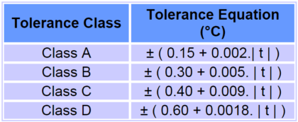
Where | t | indicated the magnitude of the temperature in Celsius (that is sign is dropped). Some manufacturers further subdivide their RTD Tolerance Classes into Tolerance Bands for greater choice in price performance ratios.
Characteristics of Platinum RTDs
The IEC751 specifies a number of other characteristics – insulation resistance, environmental protection, maximum thermoelectric effect, vibration tolerance, lead marking and sensor marking. Some of these are discussed below:
Thermoelectric Effect: A platinum RTD generally employs two metals – the platinum sensing element and copper lead wires, making it a good candidate for a thermocouple.
If a temperature gradient is allows to develop along the sensing element, a thermoelectric voltage with a magnitude of about 7 µV /°C will be generated. This is only likely to be a problem with very high-precision measurements operating at low excitation currents.
Wiring Configurations and Lead Marking:
There are three wiring configurations that can be used for measuring resistance – 2, 3 and 4 wire connections.

IEC751 requires that wires connected to the same end of the resistor be the same colour – either red or white, and that the wires at each end be different.
Sensor Marking: IEC 751 stipulates that a sensor should be marked with its nominal R0 value, tolerance class, the wiring configuration and the allowable temperature range. An example marking is:
Pt100 / A / 3/ -100 / +200
corresponding to 100 Ohm platinum, class A, 3 wire configuration and with a temperature range from -100°C to +200°C.
Measurement Current: Preferred measurement currents are specified as 1, 2 and 5 mA, although 5 mA is not allowed with class A sensors due to potential self-heating errors.
Nickel RTDs
Nickel sensors are preferred in cost sensitive applications such as air conditioning and consumer goods. Because cost is an issue, they are generally manufactured in higher resistance values of 1k or 2k ohms so that a simple two-wire connection can be used (rather than the 3 or 4 wire connections common with platinum types).
There appears to be no international standard covering the nickel RTD, although most manufacturers appear to follow IEC751 (which only deals with platinum devices) where appropriate. A resulting problem is that there appears to be no widely-accepted calibration for the nickel RTD.
One manufacturer of nickel RTDs recommends the following polynomial:
R(t) = R0 (1 + a.t + b.t2 + d.t4 + f.t6 )
where a = 5.485×10⁻³ b = 6.650×10⁻⁶ d = 2.805×10⁻¹¹ and f = -2.000×10⁻¹⁷. The alpha for this part is 0.00672 ohms / ohm / °C
More common for low to medium precision measurement the simplification of the equation is used with a = alpha:
R(t) = R0 (1 + a.t )
which is easily inverted for temperature:
t = (Rt / R0 – 1) / a = (Rt / R0 – 1) / 0.00672
where “a” is substituted for the alpha value.
Nickel is less chemically-inert that platinum and so is less stable at higher temperatures. Glass passivation can extend the useful temperature range to 200°C, but the nickel RTD is normally used for sensing in the environmental temperature range and in clear air.
Nickel – Iron RTDs
Lower in cost than the pure Nickel RTD, the Nickel-Iron RTD finds application in HVAC and other cost-sensitive applications. The alpha = 0.00518
Copper RTDs
Copper is rarely used specifically as a sensing element, but is often employed when a copper coil exists for other purposes. For example in a vibrating wire stain gauge a coil is required to “pluck” the wire and sense its vibration frequency.
The same coil can be used to sense the temperature of the sensor so that its readings may be compensated for temperature induced drifts. Another application is in measuring the temperature of electric motor and transformer windings.
In these types of applications, where temperature sensing is a secondary function, care should be taken in winding the coil so that thermal expansion of the system does not induce significant strain gauge effects in the copper wire which may add to the uncertainty of the measurement.
There appears to be no international standard for copper RTDs, however an alpha = 0.00427 ohms / ohm / °C is commonly used. When the temperature range is small (say 0°C to 180°C) and the accuracy needs are not great, a simple linear function can be used:
t = (Rt / R0 – 1) / 0.00427
Molybdenum RTDs
Molybdenum has a temperature coefficient of expansion which almost perfectly matches that of alumina, making it an ideal material for film type of construction. The useful temperature range is typically -200°C to +200°C and the material’s alpha = 0.00300 ohms / ohm / °C.
Molybdenum RTDs are also available with an alpha = 0.00385 ohms / ohm / °C (achieved by doping with other metals) which makes it compatible with the standard Pt100 devices over a reduced temperature range and at a reduced cost.
The RTD incorporates pure metals or certain alloys that increase in resistance as temperature increases and, conversely, decrease in resistance as temperature decreases. RTDs act somewhat like an electrical transducer, converting changes in temperature to voltage signals by the measurement of resistance.
The metals that are best suited for use as RTD sensors are pure, of uniform quality, stable within a given range of temperature, and able to give reproducible resistance-temperature readings. Only a few metals have the properties necessary for use in RTD elements.
RTD elements are normally constructed of platinum, copper, or nickel. These metals are best suited for RTD applications because of their linear resistance-temperature characteristics (as shown in Figure 1), their high coefficient of resistance, and their ability to withstand repeated temperature cycles.

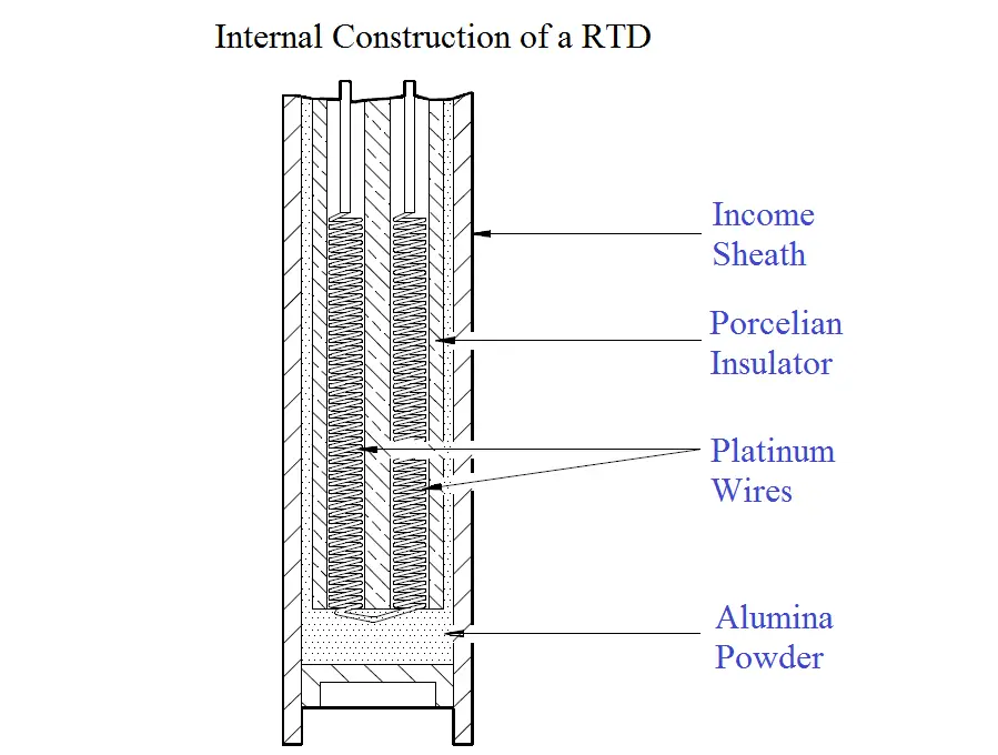
Figure 2 Internal Construction of a Typical RTD
This particular design has a platinum element that is surrounded by a porcelain insulator. The insulator prevents a short circuit between the wire and the metal sheath.
Inconel, a nickel-iron-chromium alloy, is normally used in manufacturing the RTD sheath because of its inherent corrosion resistance. When placed in a liquid or gas medium, the Inconel sheath quickly reaches the temperature of the medium.
The change in temperature will cause the platinum wire to heat or cool, resulting in a proportional change in resistance.
This change in resistance is then measured by a precision resistance measuring device that is calibrated to give the proper temperature reading. This device is normally a bridge circuit.
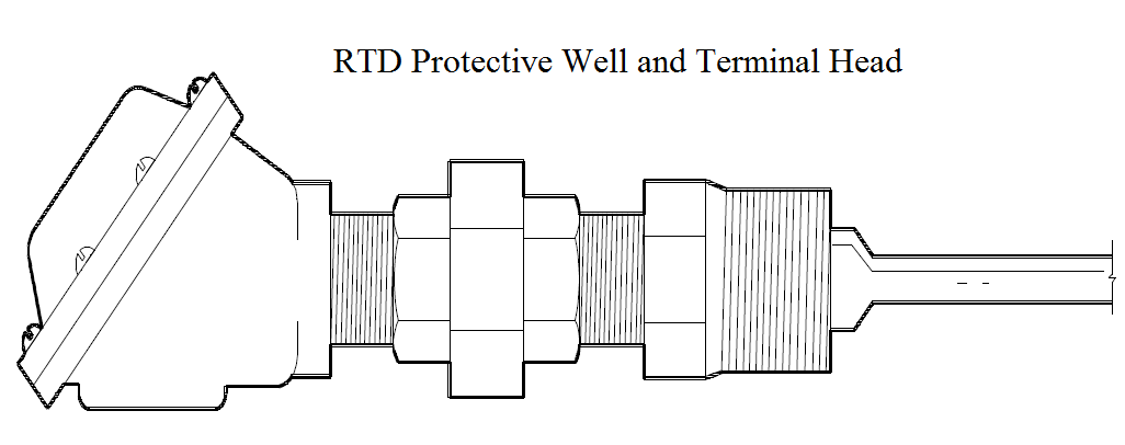
Figure 3 shows an RTD protective well and terminal head. The well protects the RTD from damage by the gas or liquid being measured. Protecting wells are normally made of stainless steel, carbon steel, Inconel, or cast iron, and they are used for temperatures up to 1100°C.
RTD Advantages and Disadvantages
Advantages:
The response time compared to thermocouples is very fast – in the order of fractions of a second.
An RTD will not experience drift problems because it is not self powered.
Within its range it is more accurate and has higher sensitivity than a thermocouple.
In an installation where long leads are required, the RTD does not require special extension cable.
Unlike thermocouples, radioactive radiation (beta, gamma and neutrons) has minimal effect on RTDs since the parameter measured is resistance, not voltage.
Disadvantages:
Because the metal used for a RTD must be in its purest form, they are much more expensive than thermocouples.
In general, an RTD is not capable of measuring as wide a temperature range as a thermocouple.
A power supply failure can cause erroneous readings
Small changes in resistance are being measured, thus all connections must be tight and free of corrosion, which will create errors.
Failure Modes:
An open circuit in the RTD or in the wiring between the RTD and the bridge will cause a high temperature reading.
Loss of power or a short within the RTD will cause a low temperature reading.
Immersion Error – Stem Conduction
With the calibration of industrial platinum resistance thermometers (RTD) stem conduction is likely to be the main source of error.
Immersion or Stem Conduction errors are caused by the flow of heat along the thermometer sheath. If the thermometer is immersed into a hot body the flow of heat will be from the body along the thermometer sheath into the ambient surroundings.
Conversely if the thermometer is placed into a body cooler than the surroundings then heat will flow along the sheath into the cool body. The temperature profile along the stem can lead to errors.
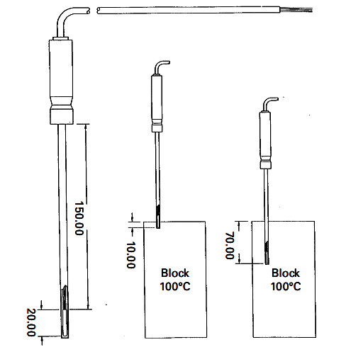
The below Figure shows a thermometer with an internal sensing element of 20mm. The thermometer is immersed only 10mm and it is clear that the thermometer will not be able to reach the temperature of the body.
The important question is, how far should the thermometer be immersed to eliminate the immersion error? This will depend on various factors including the characteristics of the thermometer and the temperature difference between the stem and the body of interest.
Various methods or mathematical models have been suggested to allow this error to be calculated but the number of variables involved make it difficult in practice to calculate the error.
From the practical point of view it may be better to immerse the thermometer as much as possible and to experiment by withdrawing the thermometer and observing any effect. It has been suggested that for metal block baths as a rule of thumb a thermometer should be inserted into the block the length of the detector plus an amount equal to 15 times the thermometer’s diameter.
For calibration of industrial P.R.T.’s in metal block baths this is likely to be the dominant source of error and will influence the uncertainty of calibration.
Lead Resistance
Resistance thermometers are, in a sense all “two wire” devices. It is when extension wires are attached to the sensing resistor that complete thermometers can become two wire, three wire or four wire connected.
Two wire devices are best avoided whenever possible. The extension wire becomes part of the thermometer and as the lead length becomes greater so does the lead resistance error.
Three wire devices can be used to largely overcome errors introduced by the extension wires. Such devices can easily be connected to electrical circuits such that the lead wire resistances cancel each other. However slight errors remain due to variations in the resistance of the individual wires.
Four-wire connection offers further improvements but industrial instruments do not always have input connections designed for four-wire connection, although laboratory instruments commonly do.
Thermal Lag
Errors due to thermal lag are those caused by the delay in the thermometer to respond to a change in temperature. Again mathematical models exist for this effect but in practice the time constant for industrial thermometers is often unknown.
For a thermometer which is in a close fitting pocket of a metal block bath (which exhibits good temperature stability) it would be usual for the thermometer to reach its final value within a few minutes. A simple observation is the best means to confirm this for new or unknown sensors.
Thermal Capacity
When a thermometer is placed into a metal block bath, heat will flow into the thermometer, or from it. This loading of the block may cause the block to change its temperature, although the temperature controller of the block will compensate to some extent.
With Standard block baths and the recommended method of using an external thermometer to measure the insert temperature such errors can be kept to a minimum. Ideally the thermal capacity of the block bath should be large compared to the thermal capacity of the probe, which will be the case for all but the largest of industrial probes.
Self Heating
Measuring the resistance of a p.r.t. requires an electrical current to be passed through the sensing resistor. The resultant power dissipated in the sensor (I2R) is often warned against. In practice, for industrial probes with modern instrumentation, it is unlikely to cause significant error.
The traditional Temperature Calibration Using Dry Block Baths 13 measuring current has been 1mA but modern instruments tend to use much smaller values that minimise any self heating, but may lead to other more significant DC errors. Users of laboratory standard platinum resistance thermometers need take more care to eliminate self heating errors.
DC Errors
Small D.C. voltages may be generated in p.r.t.’s due to thermoelectric effects caused by the joining of dissimilar metals in the construction of the p.r.t. For example the junction of copper to platinum can generate e.m.f. of 6 to 8 µV /ºC.
Resulting offset voltages can lead to error in associated instrumentation although laboratory instruments may use measuring techniques to eliminate such errors.
Thanks for reading - Resistance Temperature Detectors (RTD)
Naitik Patel
Industrial Guide
Resistance Temperature Detectors(RTDs) are widely used across several industries – power, food and beverage etc. – for temperature measurement.
In using them, different types of application problems occur once in a while. To help resolve these problems, the table below shows a list of the common problems encountered in RTD applications and possible remedies or corrective measures. This list is by no means exhaustive:
| RTD Problem | Possible Cause(s) | Remedies |
|---|---|---|
| Temperature indication generally too high | Lead resistance too high; not compensated | If possible: (1) Install larger wire size cables. (2) Compensate leads (3) Use sensor head transmitters (4) Convert to 3- or 4-wire circuits (5) Reduce connection lead lengths |
| Self heating by measuring current too high | Use a smaller measuring current(1mA current recommended) | |
| Temperature indication changes with changing ambient temperature | RTD sensor in 2-wire circuit; the connection lead are subjected to a large temperature change. | (1) Convert to 3-wire circuit, which will essentially eliminate the ambient temperature effects (2) Convert to a 4-wire circuit – in this case connection lead resistance effects completely eliminated. |
| Temperature indication error increases with increasing temperature (indication too low) | Decreasing insulation resistance, acts as a shunt path for measured signal | (1) Insulation resistance of approximately 0.1MΩ in parallel with 100Ω gives an error of the same magnitude as Tolerance Class B RTD sensors. Minimum recommendations for insulation resistance according to IEC60751 are: (a) Insulation resistance at 20°C (68°F) must be greater or equal to 100MΩ (b) Insulation resistance at 500°C (930°F) must be greater or equal to 2MΩ (2) Replace defective RTD sensor |
| Deviations of the temperature indication from the values in the table (parasitic and galvanic EMFs) | (1) Poor lead material, contamination, moisture, (2) Temperature difference between the terminals of the connection leads. (3) Corrosion at the connection terminals in the connection head. | (1) Check installation (2) Thermally insulate terminals (bring to same temperature) |
| Indication changes over the course of time | Thermal aging (drift of the measuring resistor) | (1) Select suitable high temperature design (2) Re-calibrate regularly (3) Replace sensor if necessary. |