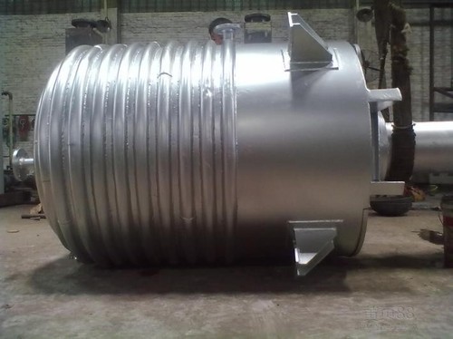
Chemical Reactors blog contains following aspects
- Chemical Reactors Introduction
- Factors influencing the choice among the different reactor types
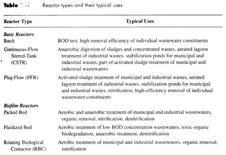
- Typical reactors used in environmental application
- Suspended-Growth Reactors
- 1. Batch reactors
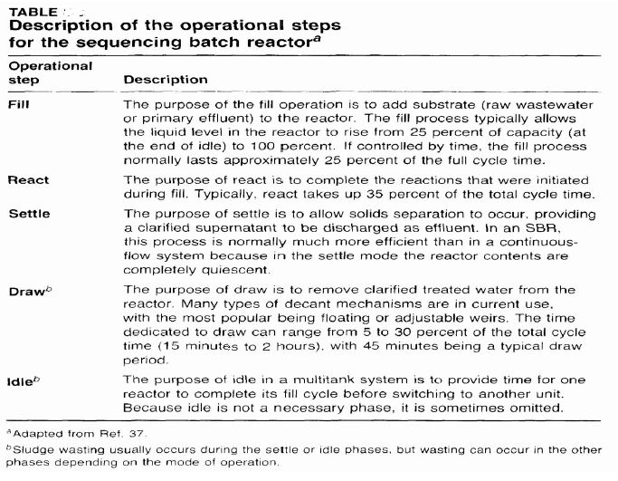
- 2. Sequencing Batch Reactor (SBR)
- Continuous-flow stirred-tank reactor(CSTR)
- Comparison of CSTR and PFR
- Practical Aspects of Reactor Design
Chemical Reactors Introduction
1. Many different types exist for environmental engineering
2. Generally designed to emphasize suspended growth or biofilms
3. That make use of suspended growth are also called:
- Suspended-floc
- Dispersed-growth
- Slurry reactors
4. That make use of biofilms are also called:
- Fixed-film
- Attached-growth
- Immobilized reactors
- Kinetics of substrate removal by different types of microorganisms
- Fundamental properties of different reactor types
- Physical & chemical characteristics of the waste being considered
- Concentration of contaminants being treated
- Presence or absence of oxygen
- Efficiency of treatment and system reliability required
- Climatic conditions under which the reactor will operate
- Number of different biological processes involved in the overall treatment system
- Skills & experience of those who will operate the system
- Relative costs at a given location and time for construction and operation of different possible reactor configurations
- How to construct mass balances for different reactors
- How to use of mass balances to derive basic equations that describe the relationship between reactor size and treatment performance.
Suspended-Growth Reactors
- The simplest suspended-growth reactor
- Biochemical reactions take place without new additions until the reaction is complete
- Commonly used in laboratory-scale
- Kinetics of contaminant removal is similar to that of an ideal plug-flow reactor
- Cyclic operation in a single reactor :
- SBR can also employ several batch reactors operated in parallel
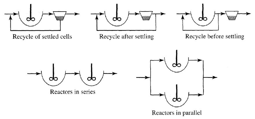
Continuous-flow stirred-tank reactor(CSTR), or completely mixed reactor :
Comparison of CSTR and PFR
Practical Aspects of Reactor Design
Mass Balances
A Batch Reactor
When t is known, S can be solved by eq 5.11.
A chemical reactor is a process equipment where in chemicals are fed in order to make them chemically react with each other for the purpose of making a desired product.
Chemical reactors are designed in such a way to increase the net present value for a given reaction and it is done by ensuring highest efficiency to output the desired product.
Types of Reactors
- Batch Reactor
- Continuous Stirred Tank Reactor (C.S.T.R)
- Plug Flow Reactor (P.F.R)
- Semi-Batch Reactor
1. Batch Reactor

A batch reactor is a closed vessel in which reactions happen and it is a non-continuous type of reactor. The reactants are fed in to the reactor all at once initially.
The vessel contains an agitator. The purpose of the agitator is to mix the reactants thoroughly so that the contact makes them react together efficiently and produce products.
In order to handle exothermic reactions the batch reactor is often equipped with cooling coils. In order to work with endothermic reactions the batch reactor has provisions for heating the reaction mixture.
The batch reactor is a non-steady, transient reactor. It means the extent of conversion within the reactor depends on time. Due to agitator the batch reactor is highly uniform in nature.
It means the extent of conversion does not depend on location within the reactor. At a given time the extent of reaction at any location of the volume of the reactor will be equal to each other.
Advantage
The greatest advantage of operating a batch reactor is its versatility.
Same batch reactor can be used to chemically react quite different variety of reactants.
Batch reactors are especially used in cases where the reaction produces lots of products.
Batch reactors are often used in labs to study kinetics of the liquid phase reaction systems.
Disadvantage
The disadvantage of batch reactor is that it requires lots of labour force to constantly charge reactants, discharge products and then to clean the reactor for the next batch.
2. Continuous Stirred Tank Reactor (C.S.T.R)
A continuous stirred tank reactor (C.S.T.R) is also often called a mixed flow reactor (M.F.R). In this reactor also the reaction occurs in a closed tank.
The tank also has agitator in order to mix the reactants thoroughly.
It is different from batch reactor in the sense that the name itself indicates it is continuous type of equipment.
Advantage
The biggest advantage of using a C.S.T.R in industries is that it can produce a large amount of products and being a continuous steady state reactor the reactor can keep on operating hours on end.
Disadvantage
The disadvantage is that a C.S.T.R cannot be used for reactions which have very slow kinetics because it will require a reactor of very large volume.
The fabrication and operational cost of the reactor may make it infeasible. Batch reactor is used in this case.
3. Plug Flow Reactor (P.F.R)
A plug flow reactor (P.F.R) is also sometime called a continuous tubular reactor (C.T.R).
In an idealised model, the profile of the reaction mixture can be considered to be made up of a number of plugs and each plug having a uniform concentration.
The idealized P.F.R model has an assumption that there is no axial mixing. It means that there is no back mixing inside the reactor.Advantage
Disadvantage
4. Semi-Batch Reactor
Advantage
The advantage of using a semi-batch reactor is that if we are carrying out multiple reactions then we have a greater control over yield or selectivity of the products.
This reactor is extremely useful when we are carrying out an exothermic reaction as the continuous flow of the other reactant can be varied to better control the exothermic reaction.
Disadvantage
If we want to scale up the semi-batch process then disadvantage over the continuous process reactors (C.S.T.R and P.F.R) is that capital costs per unit scales up relatively a lot.
Greater man power is required to charge and discharge the contents of the reactor, to clean blades, to clean reactors etc.
An agitator is a device which is used to import motion in the form of stirring to the liquids or semi solids.
The agitator is a device which contains a shaft and an impeller/propeller.
The shaft is connected to the gear box and the assembly is driven by motors using electricity.
The purpose of agitators can be for mixing liquids, solids, slurries, pastes, mixing liquids and gases, mixing solids and gases, promote chemical reactions, promote heat transfer, etc.
An agitator is installed in the vessel to ensure that the contents in the vessel become uniform and homogeneous and remain in a proper mixed state.
Since they have such wide variety of uses, the agitators are used in a multitude of industries such as chemical, process, food, pharmaceuticals, cosmetics, metal extractions, ink, paint etc.
Agitators are used in a variety of industrial processes such as for carrying out a chemical reaction, for mixing operations, for filtration, for drying, for heat exchange, etc.
The agitators are able to cater to such wide variety of applications because there are a variety of impellers which come in different shapes and sizes.
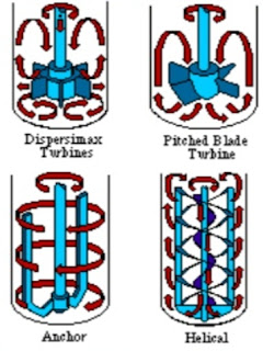
Types of Agitators
- Turbine Agitators
- Paddle Agitators
- Anchor Agitators
- Propeller Agitators
- Helical Agitators
1. Turbine Agitators
These agitators have an axial input and the output is radial.
Turbine agitators are very versatile; they are able to handle a wide variety of mixing operations because these agitators can create turbulent movement of the fluid due to the combination of rotational as well as centrifugal motion.
They are popularly used in metal extraction industries and also for chemical reactions and have a very high blending efficiency. These are mostly used in chemical, pharmaceuticals, grease, cosmetics industries.
2. Paddle Agitators
It is one of the most basic types of agitator. It contains blades which are paddle shaped; the blades stretch throughout the vessel and reach the walls of the vessel.
They are primarily used in applications where a uniform laminar flow of the liquids and little shearing is desired. This type of agitator is especially used for viscous materials.
These are mostly used in food, chemicals, pharmaceuticals, sorbitol etc industries
3. Anchor Agitators

As the name indicates the shape of the impeller resembles that of the anchor.
These agitators also extend and spread throughout the vessel such that there is very less clearance between the blades and the walls of the vessel.
These agitators are also used when laminar flow conditions are desirable. These impellers sweep the whole batch because the blades are almost in physical contact with the walls of the vessels.
These agitators are used in ink, paint and adhesive industries.
4. Propeller Agitators
These have impellers that similar to marine type propellers. They have blades which taper towards the shaft to minimize centrifugal force and to promote axial flow.
It means when this agitator operates the motion of fluid is such that the inlet flow is parallel to the shaft and the outlet flow is also parallel to the shaft, the ideal flow is axial in nature.
They are primarily used in applications to stir low viscosity liquids. They are used in pharmaceuticals industries and also other industries which use suspensions as the agitators don’t let the solid particles settle.
5. Helical Agitators
The blades of the helical agitators are arranged in a structure of helix.
The appearance is similar to how a threaded screw looks. The motion of the liquids in this type of agitator is also axial in nature due to the way the blades or the ribbons move while helical agitator is in operation.
There is a vigorous motion of the fluids within the vessel when the agitator is in operation. It is used in polymer industries and other industries which require the use of quite viscous materials.
Different types of jackets used for reaction vessels are
- Plain jacket.
- Half pipe coil jacket.
- Dimple jacket.
- Plain jacket
It can be termed as an extra covering all around the vessel or on some part of the vessel.
The annular space between the vessel wall and jacket wall is used for circulation of heating or cooling medium.
Plain jackets are suitable for small capacity vessels and for operations where pressure inside the vessel is more than twice the jacket pressure.
1. Plain jacket
It can be termed as an extra covering all around the vessel or on some part of the vessel.
The annular space between the vessel wall and jacket wall is used for circulation of heating or cooling medium.
It is most suitable where heating is to be done with steam. Jacket height is usually up to the liquid height in the vessel.
Jacket can be fabricated in one piece or can be divided into number of parts and all parts operating in parallel. For higher flow sentimental jacket is preferred when downstream vapors are used as heating medium, plain jacket is preferred.
Spiral baffling can be provided in the jacket..
It helps to induce turbulence and increase the heat transfer coefficient. A vessel with plain jacket and spiral baffles.
2. Half pipe coil jacket
Pipe is cut into two pieces and half pipe coil is welded to the vessel wall.
It helps to provide high velocity and high turbulence.
It also helps to provide strength to the vessel wall and thereby reduce the cost of vessel. It provides structural rigidity which is an advantage for high temperature operation.
To have flexibility and high efficiency the half coil jacket can be divided into multiple zones.
Half coil jacket is usually made from carbon steel. Stainless steel, monel. Inconel and other alloys can also be used for the fabrication of half coil jacket. Shows the half coil jacket welded to shell.
If jacket pressure is the controlling parameter in estimating vessel wall thickness, then half coil jacket is preferred.
These are used for high capacity vessels and where high velocities for circulating hot oils, glycols etc. is required. In these jackets by passing, short circulation is completely avoide
3. Dimple jack
It can be fabricated by using thin sheets.
It is useful for high jacket pressure operation.
Dimple jacket can induce turbulence even at very low flow velocity.
It can be used for circulating steam and hot Oil.etc.
A vessel can be provided either a jacket on limpet coil for heat transfer. Which alternative should be selected depends upon the process requirements, ease of operation and the cost involved.
Jacketed vessel ensures more heat transfer as compared to limpet coil but the heat transfer coefficient is less in jacket than in limpet coil. Pressure drop is less in jacket than in limpet coil.
Channeling of heating or cooling medium is not possible in jacket, unless spiral baffles are provided. Pumping cost is less for jacket as compared to limpet coil for the same operating pressure jacket requires more thickness than limpet coil.
Construction of jacket is easy as compared to limpet coil because in limpet coil construction lot of cutting, bending, welding is involved. Therefore jacket construction is cheaper than limpet coils.
If the heat transfer areas for jacket and limpet coils are compared it can be seen than jacket gives more surface area as compared to limpet coils.
A vessel can be provided with a jacket or a limpet coil for heat transfer in the vessel. The selection of any of the two depends upon the requirements of the process, ease of operation and the cost involved.


